Milan Technology MIL-SM8002TG User Manual
Browse online or download User Manual for Network switches Milan Technology MIL-SM8002TG. Milan Technology MIL-SM8002TG User's Manual
- Page / 180
- Table of contents
- TROUBLESHOOTING
- BOOKMARKS
- User Guide 1
- Content 3
- Introduction 9
- Software Features 10
- Package Contents 13
- Hardware Description 14
- LED Indicators 15
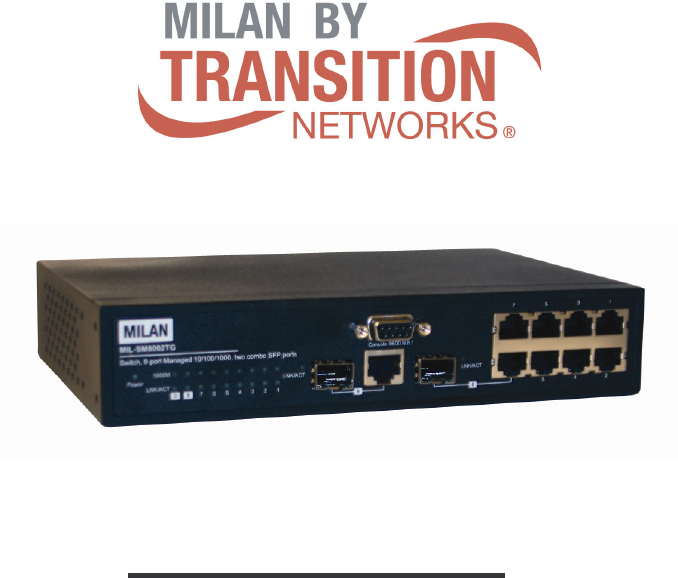
- Rear Panel 16
- Desktop Installation 16
- Power On 16
- Network Application 17
- Console Management 18
- Console login interface 20
- CLI Management 21
- Main Menu 44
- IP Configuration 47
- IP Configuration interface 48
- Firmware Update 53
- System Event Log 54
- Email Alert Configuration 57
- SMTP Configuration interface 59
- Security Manager interface 61
- Port Configuration 62
- Port Control Configuration 63
- Trunk Configuration 64
- Aggregator setting 65
- Port Mirroring Configuration 68
- Rate Limiting interface 70
- Protocol Configuration 71
- Port Base VLAN Configure 72
- Group Add interface 74
- Group Remove interface 75
- 802.1Q VLAN Configure 76
- GVRP Setting interface 78
- RSTP System Configuration 81
- System Options 85
- Community Strings 86
- SNMP V 3 Configuration 88
- SNMP v3_User Table interface 91
- QoS Policy and Priority Type 99
- Default Port Priority 100
- COS Configuration 101
- TOS Configuration 102
- SNTP Configuration 103
- IGMP Configuration 106
- Super ring 108
- Super ring Interface 110
- Security Configuration 111
- System Configuration 112
- Misc Configuration 114
- Port Security 115
- Static MAC Address 116
- Filtering MAC Address 117
- All MAC Address 118
- Load Factory Default Setting 119
- Save All Configuration 120
- Reboot System 121
- Reboot System interface 122
- Web-Based Management 123
- System Information 124
- IP Address 125
- DHCP Configuration 126
- DHCP Server Configuration 127
- DHCP Client Entries 128
- Port and IP Bindings 128
- Update Firmware 129
- Restore Configuration 130
- Backup Configuration 130
- System Log Configuration 131
- Event Configuration 132
- SMTP Configuration 134
- Security Manager 135
- Port Statistics 136
- Port Control 136
- Port control interface 137
- Port information interface 137
- Port Trunk 138
- Aggregator Information 139
- State Activity 140
- Port Mirroring 141
- Rate Limiting 142
- VLAN configuration 143
- Port-based VLAN 144
- VLAN – PortBase interface 145
- 802.1Q VLAN 146
- 802.1q VLAN interface 147
- 802.1Q Configuration 148
- Group Configuration 148
- Rapid Spanning Tree 150
- RSTP Per Port Configuration 152
- SNMP Configuration 153
- Trap Managers 155
- SNMPV3 Configuration 156
- Group Table 158
- QoS Configuration 160
- Port Base Priority 161
- Static MAC Address interface 173
- Factory Default 175
- Save Configuration 176
- System Reboot 176
- Troubleshooting 177
- Technical Specifications 179
Summary of Contents
Rev.A1 18-SEPT-2006 MIL-SM8002TG 9 Port 10/100/1000BASE-T Two Com
2 Broadcast storm filter DHCP Client, Relay, Server Per port
92 assigned. TOS only: the port priority will only follow
93 Save the configuration. Default Port Priority Setting interface COS Configu
94 COS Configuration interface TOS Configuration Set up the TOS pri
95 TOS Configuration interface SNTP Configuration You can configure the SNTP (Sim
96 Local Time Zone Conversion from UTC Time at 12:00 UTCNovember T
97 2ZP4 - USSR Zone 3 +4 hours 4 pmZP5 - USSR Zone 4 +5 hours 5 pmZP6 - USSR Zone 5 +
98 SNTP Configuration interface IGMP Configuration The Internet
99 Report A message sent by a host to the querier to indicate that the host wants to
100 IGMP Configuration interface IGMP Status When you enable the I
101 In the Super ring topology, every switch should enable super ring function and as
3 Port Trunk Support IEEE802.3ad with LACP function. Up to 3 trunk groups and maximum
102 Super ring Interface [NOTE] When you enable the super ring func
103 Security Configuration In this section, you can configure 802.1x, IP, and port s
104 802.1x Configuration interface System Configuration After ena
105 6. NAS, Identifier: set the identifier for the radius client. 7. Save the confi
106 802.1x Per Port Setting interface Misc Configuration 1. Qui
107 re-authenticated. 7. Select <Save> 802.1x Misc Configuration interface
108 MAC Address Configuration interface Static MAC Address You ca
109 4. Select <Add> to save all configure value. 5. Existed Entry: you will s
110 Add the Filtering MAC Address 1. MAC Address: Enter the MAC a
111 All MAC Address interface 2. The selected port of static MAC address informati
4 broadcast packet. Egress rate shaping supports all of packet. Rate
112 Load Factory Default Setting interface Save All Configuration
113 Save All Configuration interface Reboot System Reboot the switch in software r
114 Reboot System interface
115 Web-Based Management Web-Based management offers advanced management featu
116 2. Type http:// and the IP address of the switch. Press “Enter”.
117 bytes. System Location: assign the switch physical location. The maxim
118 Gateway: assign the switch gateway. The default value is 192.16
119 because the software keeps track of IP addresses rather than requiring an adminis
120 DHCP Server Configuration interface DHCP Client Entries When
121 device. Port and IP Bindings interface Update Firmware It provides the funct
5 Configuration upload and download Support binary format configuration file for syst
122 Update Firmware interface Restore Configuration You can restor
123 1. TFTP Server IP Address: fill in the TFTP server IP 2. Backup File Name: fill
124 Event Configuration You can select the system log events and SMT
125 Event Configuration interface Port event selection: select the per port even
126 Link UP & Link Down: the system will produce a l
127 SMTP Configuration interface Security Manager You can change web management l
128 Port Statistics The following information provides a view of th
129 Port control interface View the Single Port Information You can direct click
130 Port Trunk The Link Aggregation Control Protocol (LACP) p
131 6. If LACP enable, you can configure LACP Active/Passive status in each ports on
6 Hardware Description Physical Dimension The physical dimensions of
132 Port Trunk – Aggregator Information interface State Activity
133 Trunking – State Activity interface Port Mirroring The Port mirroring is
134 Prot Mirroring interface Rate Limiting You can set up every p
135 Rate Limiting interface All the ports support port ingress and egress rate c
136 same VLAN members. Basically, creating a VLAN from a switch is lo
137 VLAN – PortBase interface 1. Click Add to create a new VLAN group. 2. Enter
138 VLAN—PortBase Add interface 4. You will see the VLAN displays.
139 that indicates the VLAN numbers. You can create Tag-based VLAN, and enable or d
140 802.1Q Configuration 1. Enable GVRP Protocol: check the check b
141 Group Configuration interface 3. You can Change the VLAN group name and VLAN I
7 LED Indicators The following table provides descriptions of the LED statuses and
142 Group Configuration interface Rapid Spanning Tree The Rapid S
143 the value, you must reboot the switch assign path priority number. The
144 RSTP System Configuration interface RSTP Per Port Configuration
145 4. Edge: The port directly connected to end stations cannot create bridging loop
146 Enter the system name, contact, and location information. 1. Nam
147 SNMP System Configuration interface Trap Managers A trap manager is a managem
148 3. Trap Version: select the SNMP trap version type – v 1 or v2.
149 User ID: set up the user name. Authentication Password: set up the authenti
150 SNMP V3 configuration interface Group Table Configure SNMP v3 g
151 Security Name (User ID): assign the user name that you have set up in user tab
8 Rear Panel The 3-pronged power plug are located at the Rear Panel o
152 QoS Configuration You can configure Qos policy and priority se
153 QoS Configuration interface Port Base Priority
154 Configure per port priority level. Port 1 ~ G1& 2: each po
155 1. SNTP Client: enable or disable SNTP function to get the time from the SNTP se
156 CET - Central European FWT - French Winter MET - Middle European
157 4. SNTP Sever URL: set the SNTP server IP address. 5. Daylight Saving Period St
158 Message Description Query A message sent from the querier
159 IGMP Configuration interface Super ring Super ring provide a faster redundant
160 The system also supports the coupling ring that can connect 2 or
161 Security Configuration In this section, you can configure 802.1x, IP, and port s
9 Network Application Desktop Application The switch is designed to be
162 802.1x System Configuration interface 802.1x Per Port Configur
163 802.1x Per Port Setting interface Misc Configuration 1. Quiet Period: set th
164 7. ClickApply. 802.1x Misc Configuration interface Port Secu
165 Add the Static MAC Address You can add static MAC address in switch MAC table
166 Filtering MAC Address By filtering MAC address, the switch
167 All MAC Address You can view the port that connected device’s MAC address and re
168 Factory Default interface Save Configuration Save all configu
169 Troubleshooting This section is intended to help you solve the most common prob
170 Improper Network Topologies It is important to make sure tha
171 Technical Specifications This section provides the specifications of switc
10 Console Management Connecting to the Console Port Use the supp
172 Operational Temp. 0 ~60 , 5%~95%RH Operational Humidity 10% to 90
11 The settings of communication parameters After finished the parameter settings,
Regulatory Approval - FCC Class A - UL 1950 - CSA C22.2 No. 950 - EN6
12 Console login interface
13 CLI Management The system supports two types of console management – CLI
14 configuration mode privileged EXEC mode, or end. Commands Set L
15 reload Global configuration mode Halt and perform a cold restart Switch (config
16 show accounting Privileged EXEC Show username & password Swi
17 Use the duplex configuration command to specify the duplex mode of operation for F
18 flowcontrol on or no flowcontrol Interface configuration mode Use
19 State [Enable | Disable] Interface configuration mode Use the state interface conf
20 show bandwidth Interface configuration mode Display the bandwidth
21 Check OK! NEW: 2 4 Update finished!! VLAN Commands Set Commands Command Level
Content Introduction...
22 [Group name] or [VLAN ID] mode Switch (vlan)# no vlan v2 2 vlan p
23 [3584~3839] range 14 [3840~4094] range 15 VLAN protocol [Groupname] add [portNumbe
24 Priority: 32768 Mac Address: 004063800030 Root_Path_Cost: 0 Root P
25 data unit (BPDU) message from the root switch within this interval, it recomputes
26 learning states last before the port begins forwarding. Use the no
27 no qos level [priority] Global configuration mode [Priority] 0~7 0~3 LOW 4~7 HI Sw
28 show qos low-priority-delay-bound Privileged EXEC mode Show low pr
29 Mac / Filter Table Commands Set Commands Command Level Description Defaults
30 show mac-address-table [static | filter] Privileged EXEC mode Use
31 Port Mirroring Commands Set Commands Command Level Description Defaults Exampl
Port Mirroring Commands Set...
32 Stacking Commands Set Commands Command Level Description Defaul
33 802.1x Commands Set Commands Command Level Description Defaults Example show 802
34 [quietperiod value] Or no 8021x misc quietperiod configuration mod
35 set to the Authorized or Unauthorized state in accordance with the outcome of an a
36 Main Menu There are five selections as follow. System Configu
37 Main menu line interface Control Key description: The control keys provided i
38 choose the item, and press “Enter” key to select the item. Statu
39 8. MAC Address: The unique hardware address assigned by manufacturer. System De
40 name into IP addresses. Because domain name are alphabetic,
41 DHCP Configuration It short for Dynamic Host Configuration Protocol that is a pro
Port Base VLAN Configure...
42 The system provides the DHCP server function. Enable the DHCP serv
43 DHCP Server Configuration interface DHCP Client Entries When the DHCP server f
44 DHCP Client Entries interface Port and IP Bindings You can ass
45 Port and IP Bindings interface Firmware Update It provides user to update firm
46 4. File Name: type the image file name. 5. Press “ESC” to back t
47 System Log Configuration interface System Log Configuration Configuring the sy
48 System Log Configuration interface Event Configuration You can
49 Email Alert Configuration When the specific events occur, the system will send
50 Email Alert Configuration interface SMTP Configuration You can
51 SMTP Configuration interface Recipient’s email Configuration Assign the forw
Security Configuration ...
52 Recipient’s email Configuration interface Security Manager You
53 Security Manager interface
54 Port Configuration In this section, you can view port counter inf
55 Port Counter interface Port Control Configuration You can set up every port st
56 9. To view the State of Ports, select <Refresh> to get the
57 mode, more detail information refers to IEEE 802.3ad. Aggregator setting 1.
58 Trunk Configuration — Aggregator Setting interface Aggregator I
59 Trunk Configuration – Aggregator Information interface State Activity When you
60 c. If you are active LACP’s actor, when you are select
61 3. Source Port (TX/RX): select the monitor mode of each port. You can choose whic
View the Single Port Information ...
62 broadcast/multicast/unknown unicast packet, broadcast/multicast
63 Protocol Configuration In this section, you can configure VLAN, RST, SNMP, SNTP,
64 VLAN Mode Selection interface Port Base VLAN Configure Add VLA
65 Group Add 1. Group Name: Type a name for the new VLAN, ex: VLAN01. 2. VID:
66 Group Add interface Group Remove You can remove unwanted VLAN
67 Group Remove interface Group List Display the all VLAN groups’ information.
68 Group List interface 802.1Q VLAN Configure You configure GVRP
69 802.1Q VLAN Configuration interface GVRP Setting GVRP (Generic Attribute Re
70 GVRP Setting interface Configure VLAN by Port 1. Select the p
71 Configure VLAN by Port interface VLAN List Enable or disable the VLAN group. 1.
Super ring ...
72 Edit VLAN Group interface Rapid Spanning Tree The Rapid Spanni
73 Rapid Spanning Tree interface RSTP System Configuration 1. You can view spann
74 Hello Time (1-10): the time that controls switch sends out the
75 You can configure path cost and priority of every port. 1. Select the port in Por
76 RSTP Per Port Configuration interface SNMP Configuration Simpl
77 SNMP Configuration interface System Options Enter the system name, contact, an
78 SNMP System Options interface Community Strings You can change
79 3. Save the configuration. Add Community Strings interface Trap Managers A tr
80 5. To disable the trap manager, please delete the trap manager IP
81 SNMP V3 configuration interface Context Table Configure SNMP v3 context table
1 Introduction The product is a multi-port switch that can be used to build h
82 SNMP v3_Context Table interface User Table Configure SNMP v3 u
83 SNMP v3_User Table interface Group Table Configure SNMP v3 group table. 1. Us
84 SNMP v3_Group Table interface Access Table Configure SNMP v3 ac
85 SNMP v3_AccessTable interface Add Table Add the access table. 1. Context:
86 Remove/Browse Table Remove and Browse access table.
87 MIBview Table Configure MIB view table.
88 SNMP v3_MIBviewTable interface Add Table Add MIB view table
89 Remove/Browse Table Remove and Browse MIBview table.
90 QoS Configuration You can configure Qos policy and priority s
91 QoS Configuration interface QoS Policy and Priority Type Select the Oos Poli
Related products and manuals for Network switches Milan Technology MIL-SM8002TG
 (178 pages)
© 2020, manymanuals.com. All rights reserved. | 0.933 s |
 Manymanuals.com
 Manymanuals.de
 Manymanuals.fr
 Manymanuals.it
 Manymanuals.pl
 Manymanuals.cz
 Manymanuals.es
 Manymanuals-pt.com
Comments to this Manuals